I’m in the process of designing and building my first (and hopefully last) off grid solar power system to power an amateur radio repeater on my site. This has been quite the undertaking, but soon we will have 2-meter amateur radio coverage within the Steinthal Valley.
The Problem
The problem I have been faced with for years has been that my residence is in a valley with approximately 100 feet elevation of hills on all sides making it virtually impossible for operation placing a tower in the valley (and close to the residence) nearly impossible and extremely costly as the heights I would need in order to have effective VHF coverage would require a tower nearly 200 feet tall, requiring FAA clearance. Additionally, I am unable to obtain high-speed internet in the valley due to the lack of service in my location. A secondary benefit of internet service via a radio link with a local provider will finally be a reality for the property. In order to effectively kill two birds with one stone, I have elected to place an amateur radio tower in field located on the top of the hill to the northeast of the residence, but unfortunately this meant that it would be at least 1000 feet away from any power source and getting power to that location would require directional boring through a large area of wooded land. The quoted cost of just the boring would be over $25,000 and cable would be another $5,000. That simply is not in the budget for me.
The Solution
Why not build an off-grid photo-voltaic system that will allow me to install my amateur radio repeater in a more favorable location on my residence and provide me with high-speed internet at the same time? This is exactly what I have set out to do.
The Parts
- Repeater: Bridgecom BCR-50V
- Duplexers: Bird Technologies Vari-Notch (6″ cavities) Model 28-37-02A
- Antenna: Tram-Browning 6dB VHF omnidirectional antenna
- Solar Panels: Two Solarworld 320 Watt Sunmodule SW320 panels.
- Panel Mounts:
- Fiber Optic Cable: CORNING I 006KUC-T4130D20 – ALTOS Lite(TM) Loose Tube, Gel-Free, Single-Jacket, Single-Armored Cable, 6 fiber, 62.5 µm multimode (1000 feet)
- Media Converters: StarTech 10/100 Fiber to Ethernet Media Converter Multi Mode SC 2 km (MCM110SC2).
- Tower: 110′ Rohn 25.
- Charge Converter: Blue Sky Energy Solar Boost 3024iL with factory installed DUO-Option. Charges the 24v battery bank via solar panels.
- Inverter: Converts 24DC to 110V AC to power equipment.
- Batteries: Universal 12v 250 AH Deep Cycle Sealed AGM Batteries – UB8D hooked in series for a 24 V system. Each battery weighs a whopping 167 pounds! Back breakers for sure!
- Meter: Bayite DC 6.5-100V 0-100A LCD Display Digital Current Voltage Power Energy Meter Multimeter Ammeter Voltmeter with 100A Current Shunt
The Repeater System
The Radio
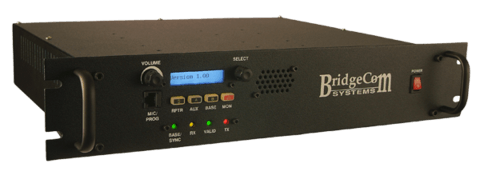
Bridgecom BCR-50V 2-meter repeater
A repeater is simply a combination of a radio receiver and a radio transmitter that receives a weak or low-level signal on one frequency and re-transmits it at a higher level or higher power on another frequency, so that the signal can cover longer distances without degradation. The repeater I own, a Bridgecom BCR-50V is programmed to receive signals on 144.850 MHz and transmits on 145.450 MHz. It will be housed along with the duplexers at the base of a guyed Rohn-25 100 foot tower in the northern field of my property.
I recently received my frequency allocation from The Wisconsin Association of Repeaters and for the sake of completeness the information regarding the repeater is as follows:
System Type: Repeater
Transmit Freq: 145.450
Receive Freq: 144.850
Callsign: NJØY
Transmitter Latitude: 43-58-44N
Transmitter Longitude: 87-59-55W
City: Kiel
State: WI
ERP (Watts): 47
EIRP (Watts): 77
Site Elevation (AMSL): 951
Antenna HAAT (ft): 163
Antenna Pattern: Omni Antenna Height AGL (ft): 100
Antenna Gain (dBi): 5.7
Primary Emission Designator: 14KØF3E
Tx CTCSS: 146.2
Rx CTCSS: 146.2
The Duplexers
Bird Technologies Vari-Notch Duplexers
Duplexers are large canisters that are tuned to the send and receive frequencies of the repeater and allow bidirectional communications to occur with one antenna. In other words, the duplexer enables the repeater to transmit and receive simultaneously on a single antenna and feedline without interference to each function by providing the necessary “isolation” between the transmit and the receive frequencies.
The Antenna
I am placing a Tram-Browning 6dB VHF omnidirectional antenna on top of the tower.
The Fiber
Finally, I plan to put a fiber media converter at the base of the tower so I can run a 1000′ fiber optical cable back to the residence allowing me to monitor and control the system remotely. The cable run back to the residence is too long for a traditional CAT5 cable which has a maximum acceptable distance of approximately 328 feet. This won’t be an issue with fiber optic cable, however, which would allow me to have a single run of several miles depending on the cable I use. I will need to convert the CAT5 input from the tower base into a fiber signal for the 1000+ foot run to the residence where I will then convert it back to a (utilizing a second media converter) to be connected to my local router at the residence.
Powering the System
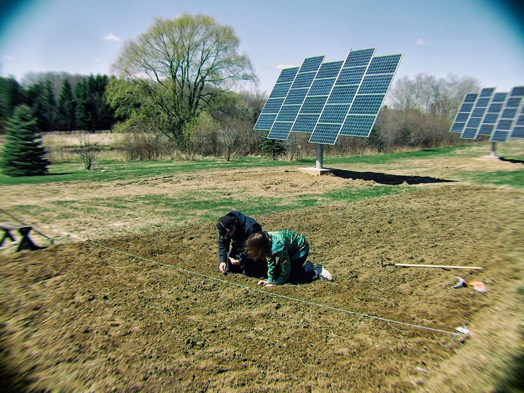
Because of the remote location, I was faced with the challenge of powering the system without access to nearby 110 VAC. I currently have a 20kW grid tied solar array on three trackers providing near all the energy needs of my residence and lodge, but this new system will be much smaller and completely off the grid.
Determining the System Size
Calculating the size of the system was a challenge and it has been somewhat difficult given the number of unknown variables within the calculation. Given my northern latitude and seemingly never-ending winters, I tried to build enough redundancy into the system to ensure that it would provide at least 3 days of autonomy (i.e. it will continue to run without any sun to charge for at least three days) and for those of you interested, this is how I calculated the system size:
STEP 1 – Calculate Average Daily Watt Hours (Wh) Needed
(AC Average Daily Wh ÷ Inverter Efficiency ) + DC Average Daily Wh = Average Daily Wh
There are many variables in this calculation. Basically, what you need to do is calculate what the total power consumption will be in Wh of all items that you plan to power with the system. For example, in my case I will be powering a 2-meter ham radio repeater. The repeater will be idle most of the day and I know that it draws about .5A when at idle.
Over 24 hours this equates to 12 Amp hours (Ah)
(0.5A X 24 hours) = 12 Amp hours.
(12 Ah X 12 VDC) = 144Wh per day while idle
When transmitting at full power (50 W) it actually draws about 8 amps. Assuming 1 hour of transmitting operation a day = (8A X 1 hour) = 8Ah
(8Ah X 12 VDC) = 96Wh per day at full power
So total daily power consumption of the repeater will be around:
(144Wh + 96Wh) = 240Wh per day.
I will also have a fiber media converter which I calculated will use a total of 288 Wh per day.
Finally, I have built into the system an additional load of 2Ah at 12 volts for additional radios and internet routers for a total additional power consumption of
(2A X 12 VDC X 24 hours) = 576Wh.
So my average daily Wh needed will be (240Wh + 576Wh) = 816Wh
This is probably overkill, but my primary concern is to ensure without any doubt that in the dead of winter (when the batteries are cold and there is limited daily sun available at my location) I have a system that is up and running 24 hours a day, 7 days a week.
STEP 2 – Determine the battery bank capacity in Wh
(Avg daily Wh) X (Days of Autonomy) X (Battery Temperature Multiplier) ÷ (Discharge Limit) = Battery Bank Capacity in Watt Hours
The number of “Days of Autonomy” is the number of days the system would run without any sun to charge the batteries. I am going to choose 3 days of autonomy. “Discharge Limit” is the percentage of discharge the system is allowed. In order to ensure longevity of the battery system, I am going to try and not allow more than 50% discharge. Therefore, I want my system to last for three days with no sun after which there is still 50% charge remaining (again more wiggle room if the weather gets unbearably bad in the winter). Finally there is a battery temperature multiplier that takes into account the average temperature of the system and the fact that the batteries will be much less efficient at lower temperatures.
[table id=1 /]
Because of my extremely cold winters (at least in my mind), I will use the worst case scenario of 20 degrees which gives me a multiplier of 1.59.
My equation would therefore be:
816Wh X 3 days X 1.59 ÷ .50 = 7,784 Wh
STEP 3 – Determine battery bank capacity in Amp hours (Ah)
As you probably already know, Ohm’s Law states that P=IE or Power = Current (I) X Voltage (E). So in order to calculate the current (I) we simply apply this law to our equation and solve for I.
(Battery bank capacity in Wh) ÷ (System Voltage) = (Battery Bank Capacity in Ah)
Since I have chosen to use a 24 V system, my equation would look like this:
7,784 Wh ÷ 24 Volts = 324 Ah
STEP 4 – Determine the number of parallel strings
Batteries can be connected in series (i.e. positive pole to negative pole) which will effectively increase the overall voltage of the system, but the current will remain the same. They can also be connected in parallel (i.e. positive pole to positive pole and negative pole to negative pole). This effectively maintains the system voltage which will be held at a constant and is identical to the individual voltages of the batteries, but the actual current (Amps) will increase in additive fashion to the whatever the value is for each battery. So for example: Two 6 volt 200Ah batteries hooked in series will result in a 12 Volt 200 Ah system. The same batteries hooked in parallel will result in a 6 Volt 400 Ah system. I will need something in the neighborhood of 324Ah at 24 volts. I have decided that two 12V batteries rated at 250 Ah each should probably do the job. In my case, I have decided to use Universal 12v Batteries 250 AH Deep Cycle Sealed AGM Batteries (UB8D) hooked in series for a 24 V system I will therefore have a 24V system and 250Ah. I can always double my AH in the future if needed by adding two more batteries and a second parallel string.
STEP 5 – Determine the number of batteries in each series string
(DC System Voltage) ÷ (Battery Voltage) = # of batteries in each string
I am going with a 24V system and 12V batteries.
24V ÷ 12V = 2 batteries per string
STEP 6 – Determine the total number of batteries needed for the system
(# of Series Strings) X (# of batteries in each series string) = Total # of batteries needed
In my case as I have discussed above, I will have one string of two batteries for now. I may add to that if needed in the future.
The Battery Box
I originally planned on making a battery box and placing it at the base of the tower, but after more thought I decided the better thing to do was to build a small shed and insulate it so that I had a more secure structure on site for all the gear.
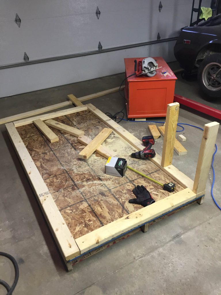
Battery box construction will be more than large enough to house the batteries, charge converter and inverter for the system…
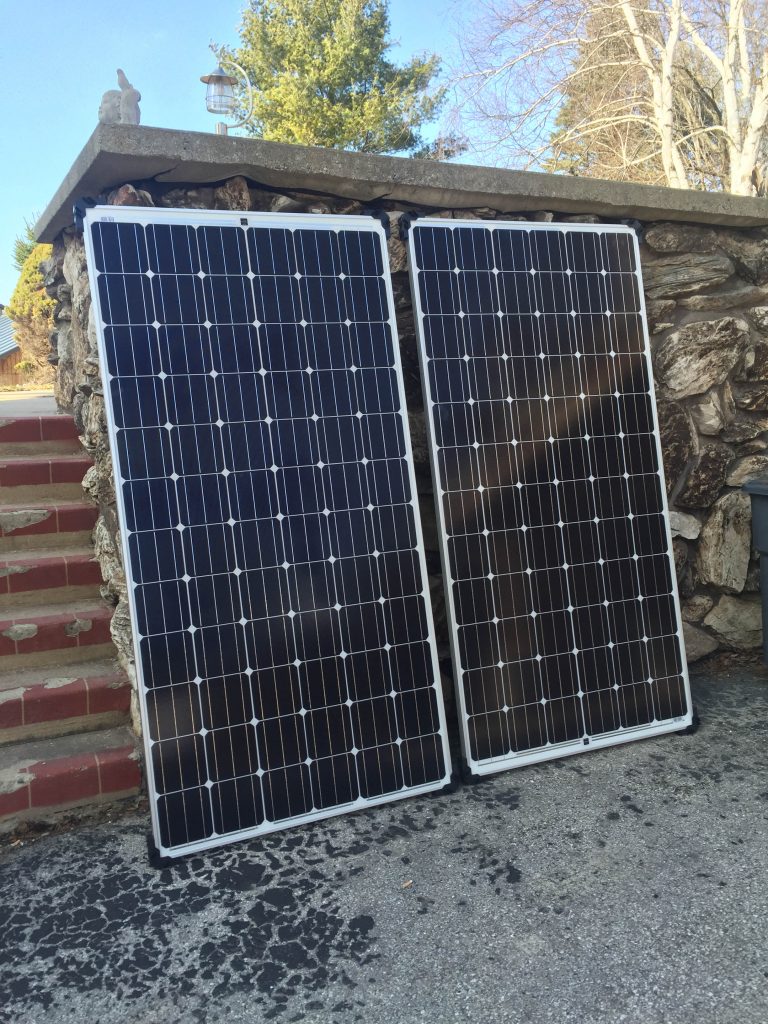
Solarworld 320 W panels delivered and ready for install
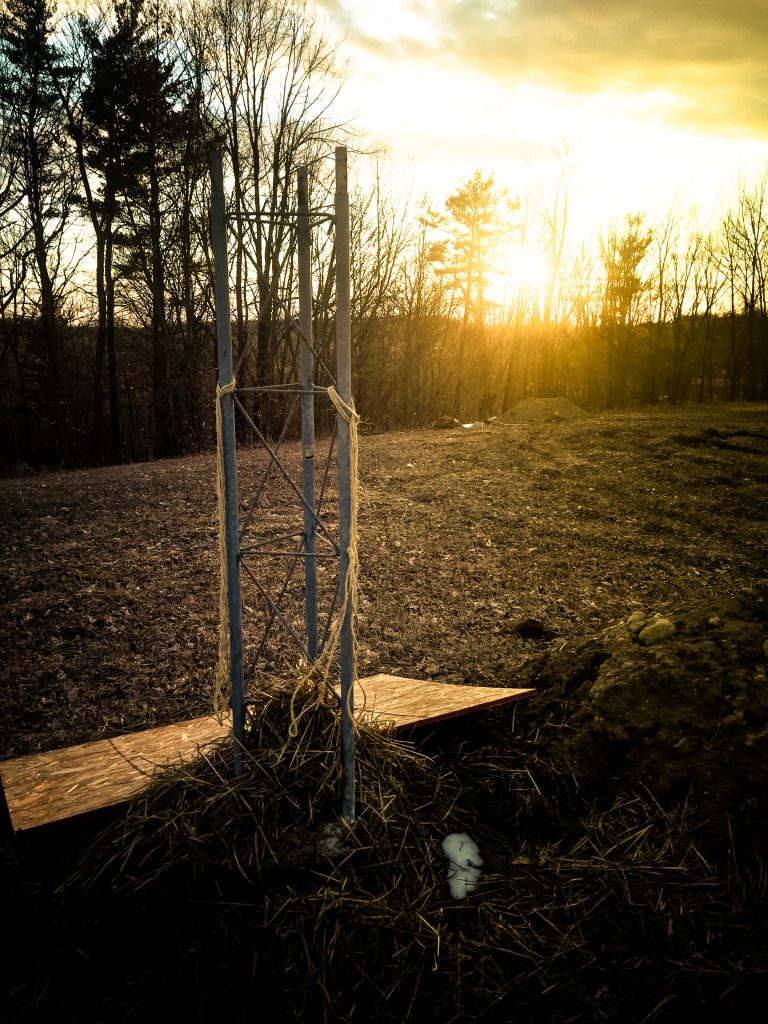
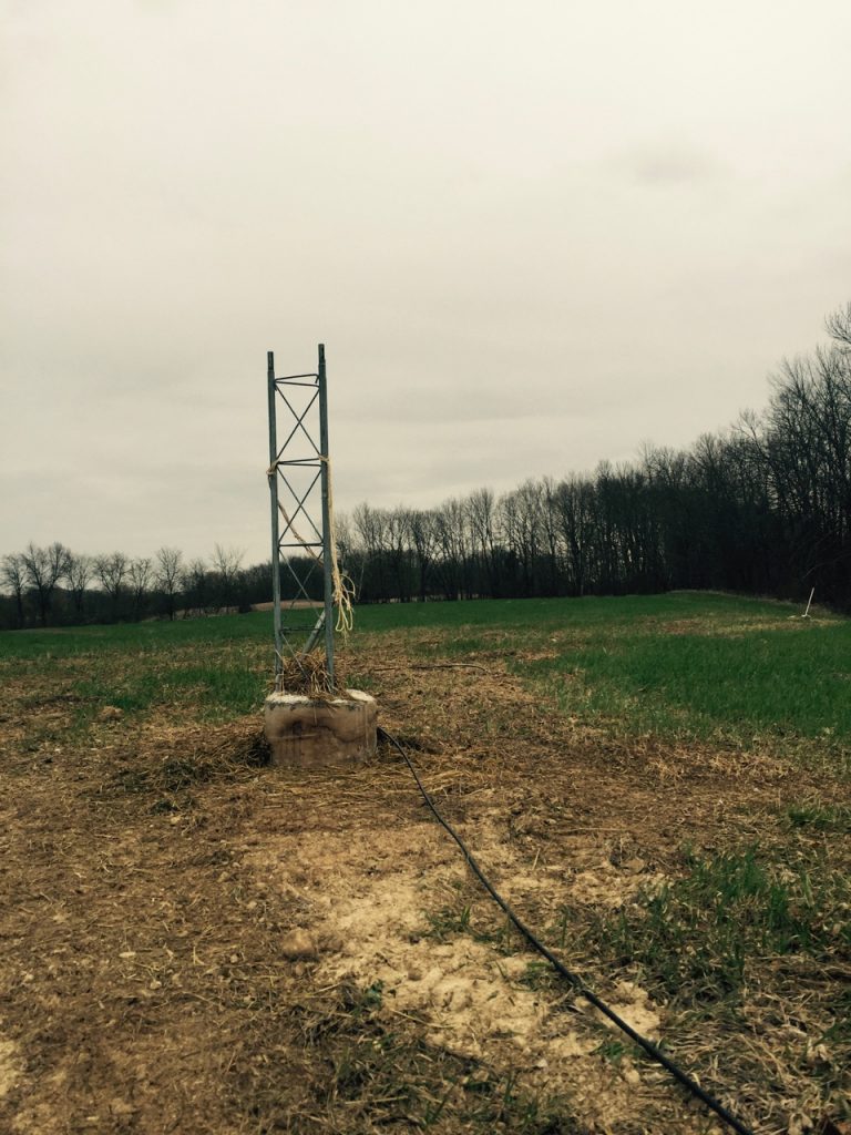
The Rohn-25 tower base in place and ready to be extended.
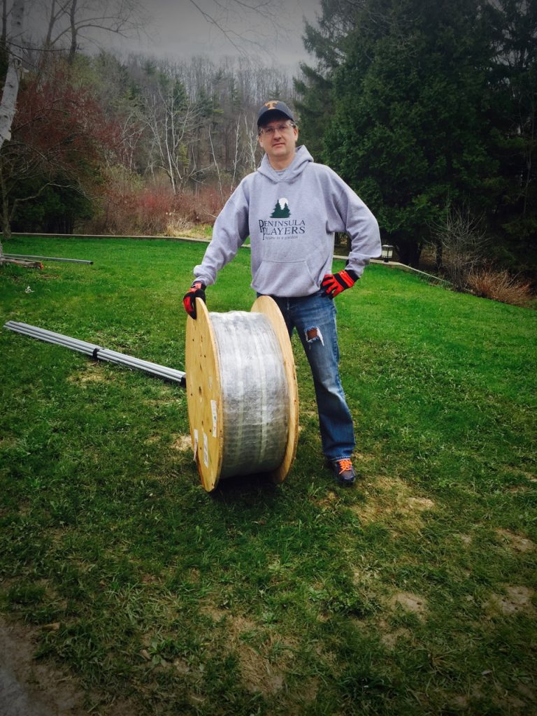
In “Weekend Warrior Mode”, even though it’s Thursday….
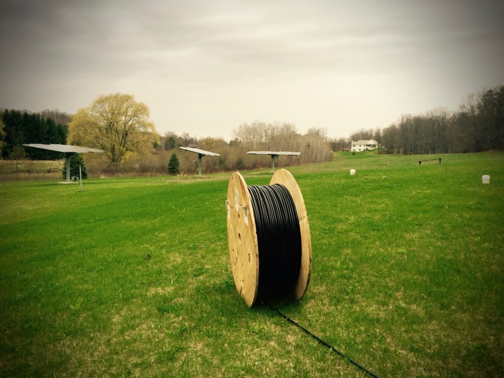
Rolling the fiber into the field prior to trenching
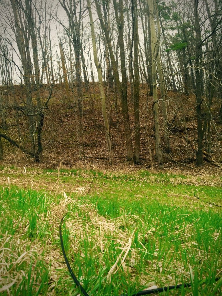
The not so enjoyable task of pulling cable up a 100+ foot hill, through dense woods in the rain…
When I got through the woods, I further tweaked the location of the fiber and later this weekend I will begin the process of trenching and burying the cable. The portion through the woods will ultimately be placed in conduit for added protection. The cable is armored already, but I really don’t want to have to worry about this leg of the fiber run.
Finally made it to the top of the hill and through the woods 1000 feet from the residence! And it was raining too!
This weekend I will begin trenching and getting the cable buried. I have to complete the battery box on site and hope to get that completed by Tuesday May 3rd at when the fiber will be terminated in the residence and at the base of the tower. May 10th will mark the completion of the tower and placement of the antenna. I will be very busy over the next couple of weeks hoping I can get everything coordinated as planned….. WISH ME LUCK!!!